We all need to know there’s a way out
Chapter 1 set the brief: sixteen cylinders, roughly ten litres, natural aspiration and a maximum-speed target of 9,000 rpm. Splendid. Put the kettle on. We appear to be designing an engine.
Then came the awkward question: where are we going to put everything?
The crankshaft needed room to turn. The cylinder liners occupied much of the neighbourhood. The camshaft drive needed gears, bearings and supports. And we wanted to take things apart afterwards without dismantling half the engine.
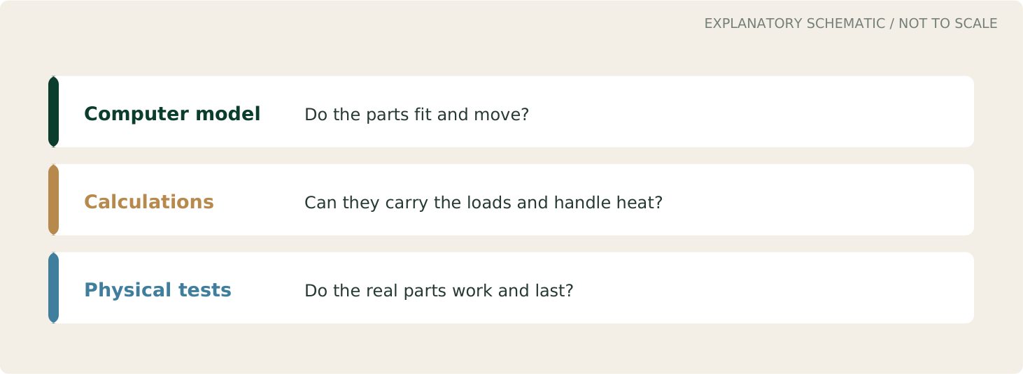
This is the story of finding that arrangement. It covers development through October 2026, with some questions still open. Fitting together on a computer with the help of CAD is progress; running reliably on a test bed is another matter.
Reading the drawings
Green: structure and reference geometry. Gold: drive, fastening and change. Blue: fluid routes or service motion. Red: a conflict or applied load.
Give everything an address – where does everything live?
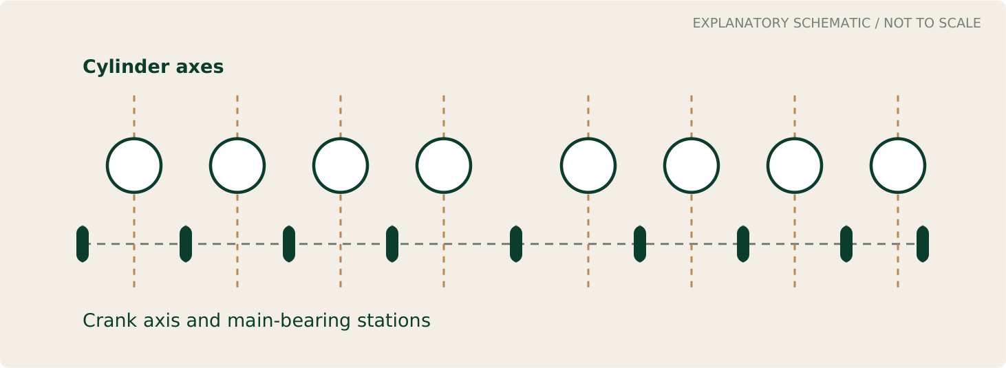
Before drawing the interesting bits, we marked the cylinder centres, crankshaft axis and main-bearing positions. These reference lines formed the engine's skeleton. There wasn't much to admire, but there was something reliable to measure from.
The crankshaft turns the pistons' up-and-down movement into rotation. Connecting rods link the pistons to eight shared crankpins, with two rods sitting side by side on each pin. Nine main bearings support the crankshaft.
Those rods, bearings and the metal between them all need space. Changing one dimension can affect the whole engine, so the parts have to develop together.
We also wanted readily available, unmodified bearing shells: the replaceable bearing surfaces around the rotating journals. Better to design around suitable standard parts than leave a future owner hunting for something unique.
The outside shape could wait. It would be irritating to design a beautiful case and then discover that the crankshaft required a different one.
The crowded middle
The camshafts operate the valves. They must turn at half crankshaft speed and remain accurately timed to it. That requires a drive system, complete with bearings, supports, lubrication and sealing.
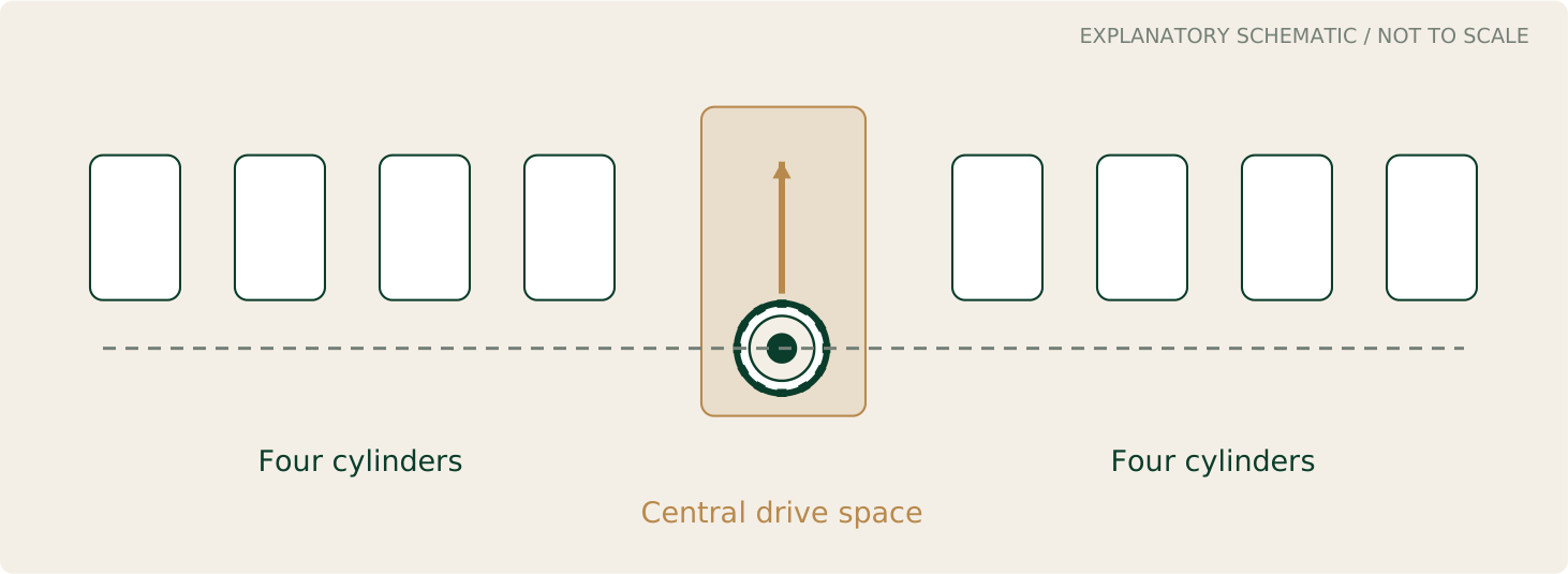
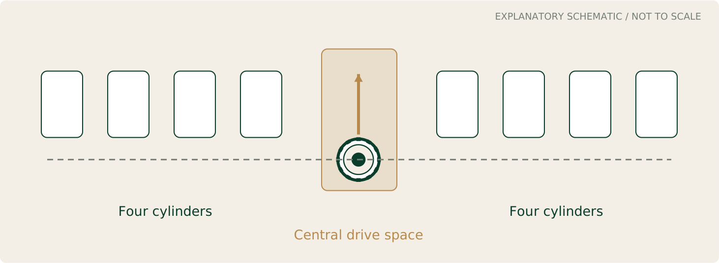
We explored putting this machinery in the middle of the V16, rather than automatically adding it to one end of an already long engine.
We called the space the cam-drive vault. A grand name for what essentially is a crowded mechanical cupboard.
Unfortunately, its neighbours were already established and living in their homes: crankshaft, main-bearing structure and cylinder liners. Persuading one neighbour to move can upset their new neighbours - and we all know how testing neighbours can be …
A central drive doesn't automatically make an engine smoother or eliminate twisting in its shafts – although eight short shafts are better than 4 much longer ones. Those questions need calculations and tests. First, we needed an arrangement that fitted, could be supported properly and could eventually be serviced.
It was a useful place to concentrate our efforts. If we could sort out this busy neighbourhood, we'd know much more about the shape of the engine around it.
The jackshaft gets an audition
A jackshaft is an intermediate shaft carrying drive from one place to another. When the direct route is blocked, it offers an obvious temptation: go round the obstacle.
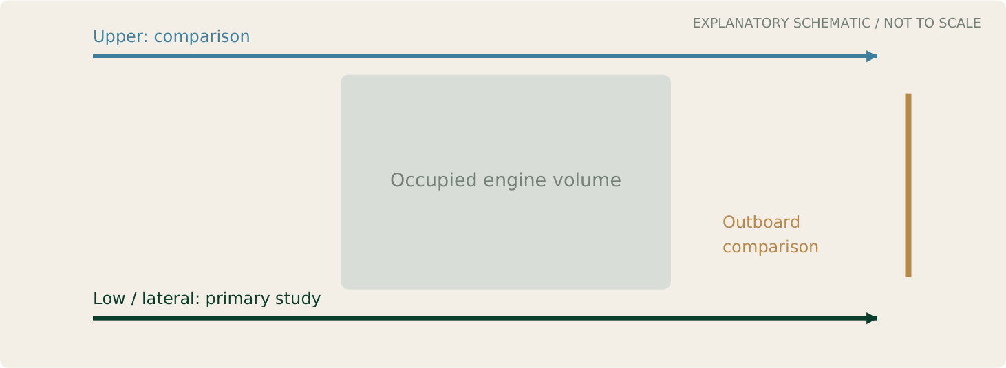
Accompanied by a lot of head-scratching (excuse the pun …) we investigated a low route beside the lower engine structure, taking drive from the front of the engine to the centre cam drive by means of a jackshaft. We examined different possible jackshaft routes. Perhaps moving the drive would give the gears more breathing room.
But the shaft brought its own luggage: bearings, supports, oil supply and extra connections. One study found a promising local gap alongside six clashes between the drive housing and liners. Clearance on one side doesn't compensate for overlapping parts on the other.
There was also stiffness to consider. A shaft twists slightly under load. Make it longer and it generally twists more; make it thicker and it takes up more room. Movement in the supports can also disturb how the gears meet.
Jackshafts work well in plenty of machines. Ours needed to justify itself. The preference remained a direct central drive, with a jackshaft acceptable only if we could establish suitable stiffness.
Look over the fence first
After many cups of tea, we eventually paused the jackshaft work. Before adding more components to get round the crowded centre, could we simply give the direct drive more room?
Like a homeowner planning an extension, it was worth looking over the fence towards our neighbours before committing to more building work. There might be a better answer to the space problem.
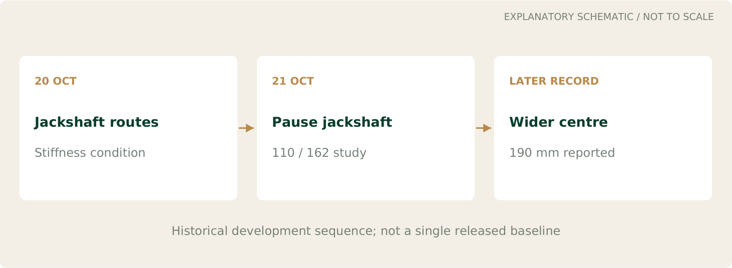
One development arrangement used 110 mm spacing within the cylinder groups and 162 mm across the centre. Later notes report a 190 mm central interval after further liner and block studies. These were successive investigations, rather than descriptions of one finished assembly.
The wider gap helped the drive but affected the crankshaft, block and cylinder-head relationships. Covers, passages and supporting structure had to follow. Extra room came with a bill attached.
Even so, it was worth exploring. Keeping the engine compact is useful; making it so compact that the parts overlap is less useful.
The jackshaft investigation hadn't been wasted. It helped us compare the alternatives and decide where to spend the space.
Measure the suitcase, not the clothes inside it
The liners are replaceable sleeves in which the pistons run. Our chosen wet liners also have coolant around their outer surfaces.
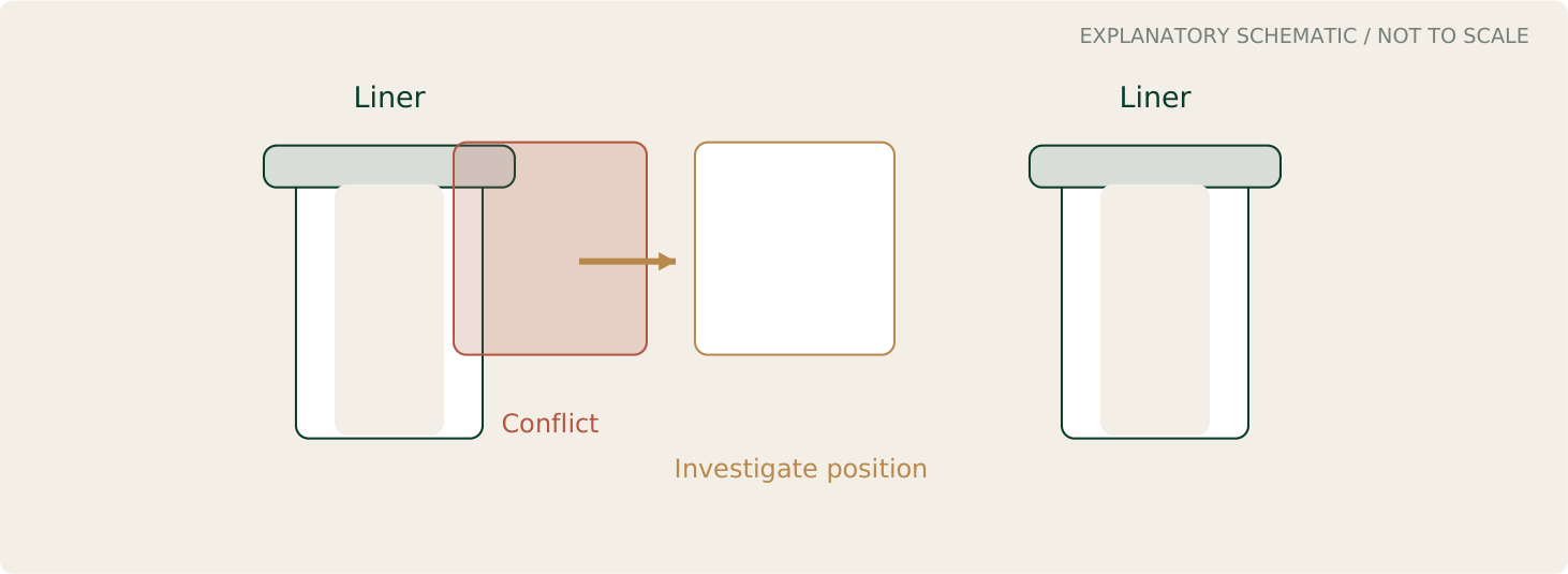
We wanted an available 96 mm-bore component, but the bore is only the hole inside it. The liner's body, top flange and lower end need accommodating too.
It's like putting a suitcase into a car boot. You can't simply measure the clothes and then wonder why the suitcase still doesn't fit.
Some early drive-housing arrangements collided with the liners. We investigated moving the housing relative to the crankshaft and cylinders. Drawing a smaller, irregularly-shaped imaginary liner would have been quicker, but the supplier was unlikely to send us one.
Cutaway views exposed conflicts hidden by a respectable-looking outside. They also helped us consider the surrounding walls and corners: enough metal for support, enough clearance for neighbours and a shape a cutting tool could actually reach.
Using a standard liner made us face those real dimensions early, while changing the design was still affordable.
Getting everything out again
Once the cam gears had somewhere to live, they needed firm support. Gears push against each other as they transmit drive. If their supports move too much, the teeth no longer meet properly.
One study explored fixed spindles, with gears turning on bearings around them. Supporting plates held the arrangement in place. The remaining questions included strength, bearing life and access.
Then came the workshop favourite: 'Yes, but how does it come out?'
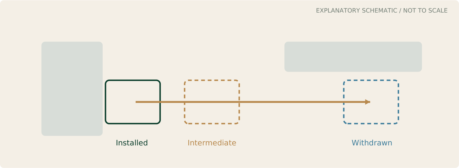
We wanted the drive cartridge, the grouped drive assembly, removable with crankshaft and liners installed. That meant checking its whole journey, including awkward positions halfway out.
A study reported about 2.2 mm clearance when installed and 1.8 mm along the removal path. Later work reported withdrawal with the major neighbours in place, but the narrow margin prompted a request for more room to avoid nudging the neighbours.
Servicing shouldn't require perfect parts, an exceptionally steady hand and a favourable phase of the moon.
The crank refuses to stay still while we measure it
A crankshaft holds any position we choose for a computer picture. In service, it has other plans.
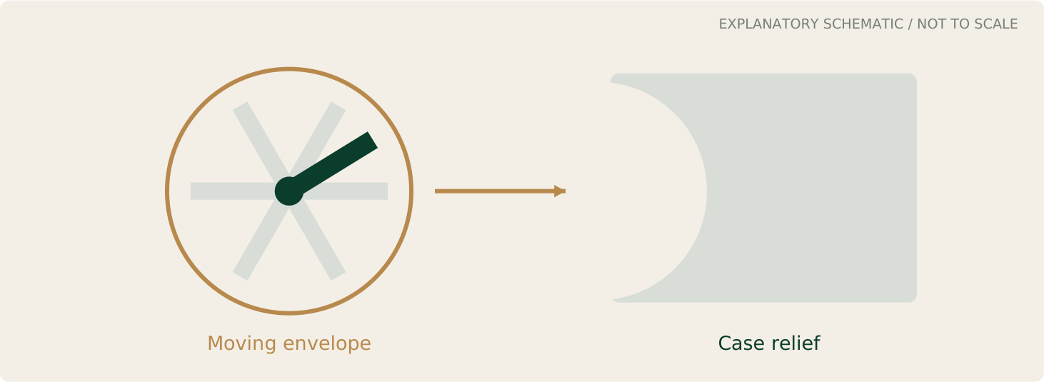
Its webs and counterweights need room throughout rotation. Later work reported a checked envelope containing the moving crank, providing a better clearance guide than a few reassuring pictures.
A reported gap of only 0.059 mm near a rear bearing relief showed why this mattered. That was a reason to investigate, not celebrate.
The envelope helped guide where case material needed relieving. Heat, bending and manufacturing variation still need allowances. We'd prefer the crankshaft not to finish-machine its own accommodation 😉
Studs meet the oil supply
We began investigating four studs at each main-bearing station, drawing on the Jaguar V12 precedent. More studs can help distribute clamping, provided the surrounding structure supports them properly. Famed race engine builder, the UK’s Rob Beere, claims the standard Jaguar V12 bottom-end is bullet-proof – needing very little modification for racing.
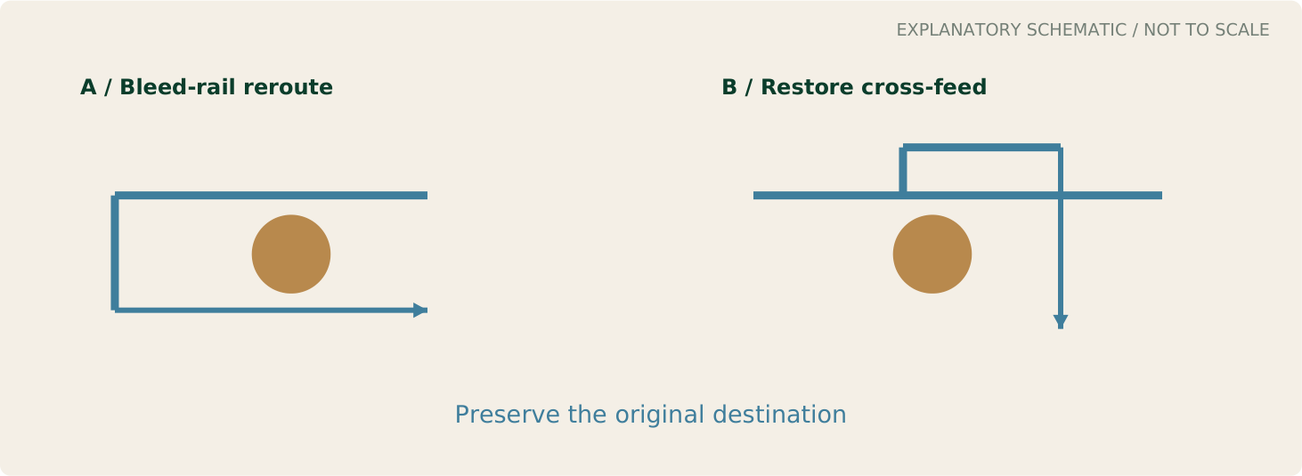
These studs also need room. Central studs must respect the timing space; others encounter oil passages.
Moving a passage around a stud only helps if the oil still reaches its destination. One location needed a diversion; another required a separate bypass to restore a connection.
Similar-looking positions didn't mean identical solutions. Finding that out in the model was considerably cheaper than discovering it after machining.
Give the seal an exit
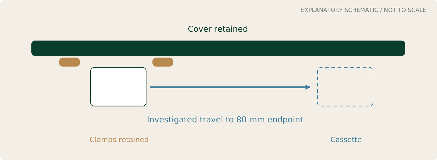
There needs to be a replaceable seal at the end of each head to allow cam line boring. I really didn’t want to simply push some sort of elastomer bung into its place. The cam covers rely on fitted continuous O-rings and positive stops to prevent over-tightening of cam covers and seal distortion. I didn’t want to compromise this arrangement and risk oil leaks. A small seal can organise a surprisingly large dismantling job. We'd rather this one didn't.
We designed an end-seal cassette to achieve this.
The study also reported separation around coolant spaces. These were computer checks, not a pressure test or proof of access in a finished car.
Still, servicing was helping shape the design early. Better that than a workshop instruction beginning, 'First remove most of the engine ….'
Where we have got to
The engine is becoming more real. Its parts have neighbours, supports, oil supplies and ways to leave the assembly.
The jackshaft investigation, wider centre and removal studies have answered useful questions. Strength, bearing life, lubrication and heat still need analysis and testing. The complete cylinder head remains a substantial job too.
There will be more changes. Better now than after we've filled a crate with expensive aluminium.
We understand more about what fits, what doesn't and what to investigate next. Sixteen cylinders still seems a splendid idea. It's certainly keeping us occupied between cups of tea.